

________________________________________________________________________________________________________________________________
One possibility for an Electro-luminiscent material is to use Organic Light Emitting Diode (OLED) .... shown in the video below is an OLED development : a Television developed from OLED which reverts to the transparent state of the material when which switched off. OLED would be ideal because the amount of sunlight entering an enclosure (( and also at different locations around the enclosure )) could be controlled.
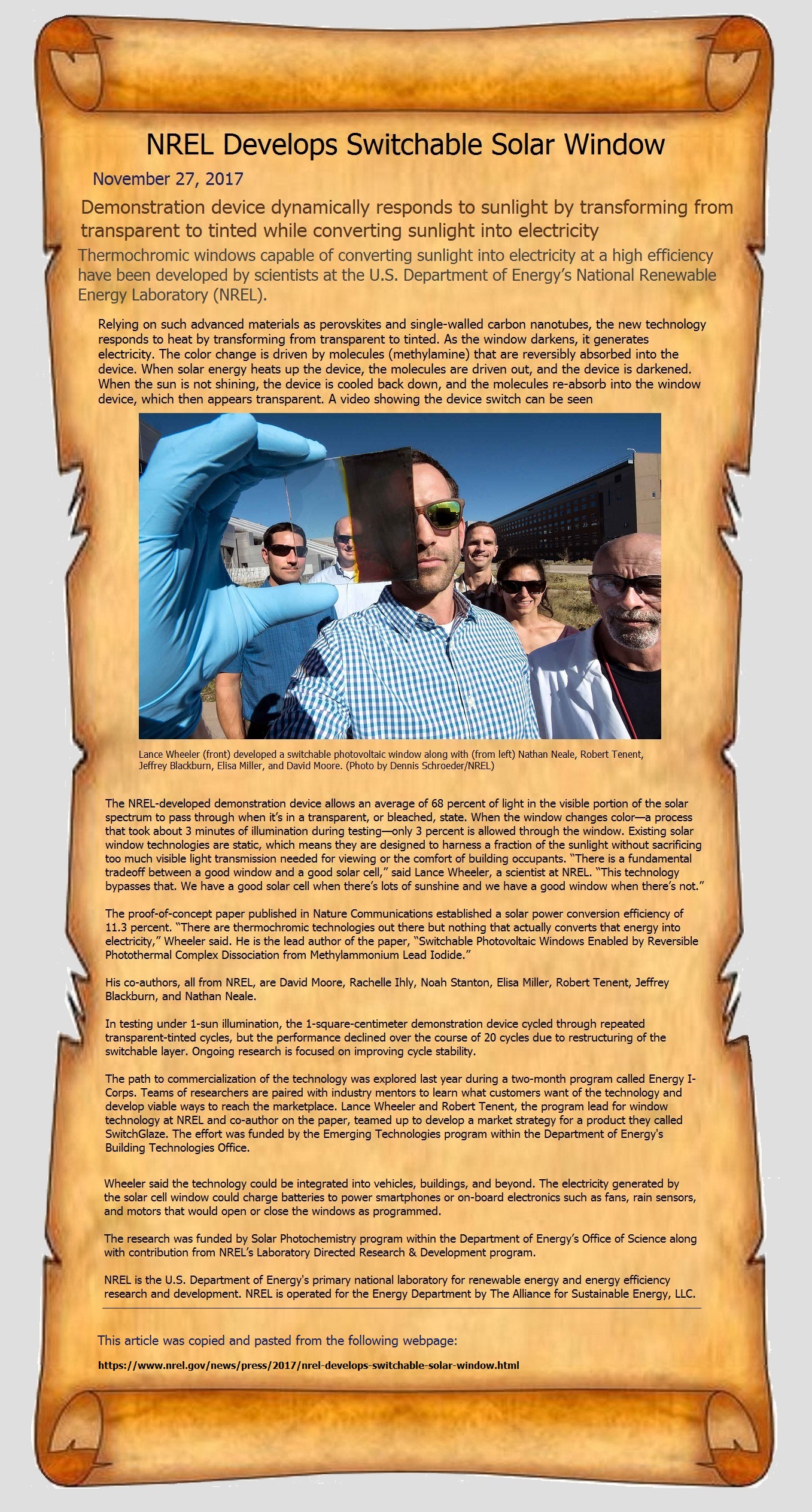
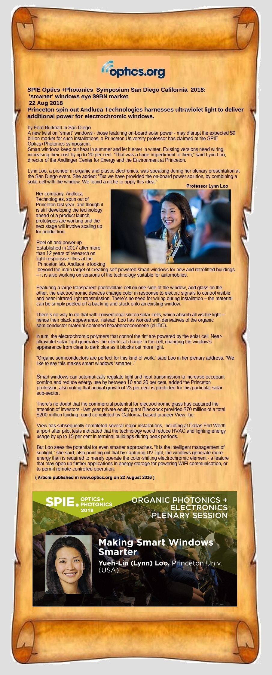
The Architect who designed this layout for this Embassy was Jacques Aizac (1950-2010) This was NOT his design. He followed instructions given by the Prophet RAEL
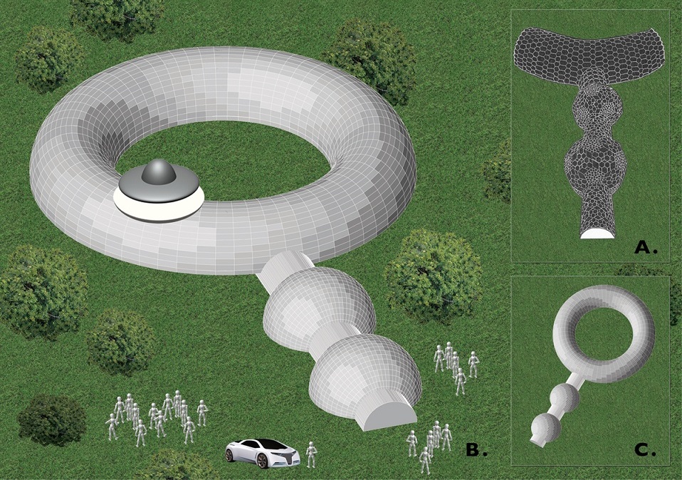
A method by which these kinds of structures can be
constructed is shown in the following U.S. Patent. Link is embedded.
More detailed information on the method will be added to this webpage
as it comes available, as the method is used.
The method of constructing domes and tubular corridors shown in this
patent (above) is a task and challenge for Mechanical Engineers. Thus,
shown below is equipment needed for a machine/patterning workshop.
The laying of the foundations ((upon which the structure will be layed ))
will be a task for Civil Engineers. A Robust foundation is essential.
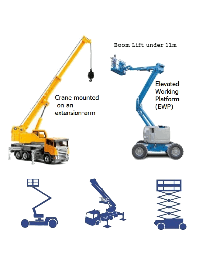
Also, shown below are a crane and elevated working platform needed in the assembly.
As is explained in
the patent specification, the structure is assembled from the top downwards,
and it can only be constructed from the top downwards, and as one continuous
structure. Thus, precise operation of the cranes is essential.
Patterning Workshop;
The method of construction shown in the link above requires a patterning/tooling
workshop wherein the patterns can be made. The patterns are then sent to a foundary
where the parts can be produced from sand cast molds. The patterns can be made using
a 3-D printer. But some 'difficult' patterns might need to be made "by hand" from timber.
Equipment needed for the patterning/tooling workshop are shown below.
It might be of interest to note that the method shown in the Patent ((link is above ))
is ideal for a 3-D printer to be utilized to make the patterns. Actually, there is
no other known method of constructing Geodesic domes where the use of a 3-D printer would
be viable to make the patterns......ofcourse a 3-D printer could always be used..... but
it would not be viable for other methods that are known so far.
Parts needed to be cut by CNC machines;
A CNC Laser cutting machine is needed to cut out flat brackets for creating the
'difficult' patterns used to join the spheres to the corridors and also for cutting
out the hexagonal and pentagonal windows from sheets of Acrylic or sheets of other material.
The CNC water-jet cutting machine is NOT essential but it could be useful in
cutting out parts from materials which cannot be cut using a laser
Industrial Gulillotine;
It is essential to note that an industrial guillotine is required to cut
the sheet of insulation material for the Gaskets
Installation of windows
The installation of the outer windows will take place inside the dome. Thus a small
vehicle with an elevated work platform suitable for operating inside the dome will be
required. The outer windows are attached using 'L' brackets bolted to the interior faces
of the frustums. The ideal bolts to use will be HEX-CAP bolts with spring washers.
Using HEX-CAP bolts the fastening task will be relatively easy when using 'L' shaped
Alum keys (especially considering that this fastening task will be an awkward).
A substantial amount of silicone sealant will be required for the windows
Hand-held machine tools;
Besides the equipment shown, other hand-held tools could be required (that are not shown):
An electric drill and electric router would also be required if it is desired that the interior
face of the frustums be a covering of Timber (instead of ceramic). In this case an electric
router will be required to cut out the centre groove (see figure 12 in the patent: link is above)
Also, what is NOT shown is the electrical equipment needed to implement the electronic control
system operating the windows
labeling of joining edges;
It is essential to note that the construction of a prototype structure using this geodesic structural innovation
as a Research and Development project; that the prototype can be designed and assembled in one location
and then dis-assembled and re-assembled as a permanent structure in another location. For ease of re-assembling the
prototype it is neccessary that each edge of each frustum be labeled such that two matching labels will be stuck on
two joining edges. Also, ( and to reiterate ) this geodesic structural innovation is assembled from the top
downwards
In this video (link embedded in picture) a Geodesic Dome had been
constructed using this method. The Dome was constructed on the 17th May 2020.
Duration of the video is 7 minutes and the file size of the video is 352 Mbytes
The video abve (posted on youtube) can be downloaed by clicking onto the download icon (below)
In the video there are 2 examples that are shown. Example 10 and Example 11. The solutions to these examples are shown on the webpage embedded in the link below

